One: Basic knowledge of mechanical drawing:
1: Reading and measurement of part size:
The basic tools for measuring the size of parts in the workshop: tape measure and vernier caliper.
1.1: The distance of one tape measure is 1mm.
1.2: The reading method of vernier calipers.
1.2.1 Take the reading of the 10-point vernier caliper as a column:
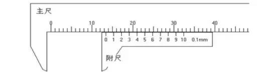
Correct pronunciation: three steps
1. Read the scale value of the main ruler first, the precision is 1 mm. The “0” scale of the attached ruler is located between “13” and “14” of the main ruler, so the main ruler scale is 13 mm. 2. Then look at the attached ruler and the main ruler. The scale where the ruler overlaps. The precision is 0.1 mm (marked at the bottom right corner of the attached ruler). The “4” scale on the attached ruler overlaps the main ruler, so the attached ruler scale is 0.1X4=0.4 mm 3. Add the values of the main ruler and the attached ruler The upper scale represents 13.4 mm
So the reading of the vernier caliper is: 13.4mm.
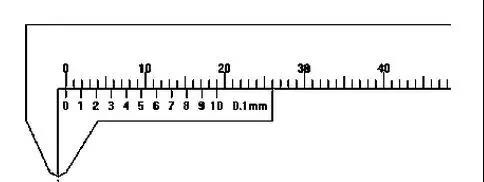
1.2.2 Zero reset of vernier caliper.
1.3 Briefly explain how to read the qualified dimensions of parts marked with dimensional tolerances:
The dimension of the sheet metal part is marked with the qualified dimension reading after the tolerance. Through the following examples to explain in detail.
For example 1:
, Its meaning is expressed as follows: +0.3 means to take the tolerance. -0.5 logo to remove the male
difference. Therefore, the qualified size is: 80-0.5 to 80+0.3, that is, 79.5 to 80.3 is the qualified size.
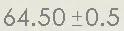
Another example 2:

, It means that the qualified size is between 64-0.5 and 64+0.5. That is: 63.5 up to 64.5 is the acceptable size.The pronunciation of other sizes can be deduced by analogy.
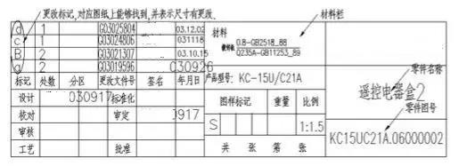
1.4 The following is the content of the title column of a drawing. The title bar is located at the lower right corner of the drawing frame, the name of the part, drawing number,designers, materials, etc. must be clearly expressed in the title bar.
2: Knowledge of mechanical drawing and comparison of drawings, quick recognition method of flipping parts:
2.1 The concept of mechanical drawing: the engineering used in the process of design, manufacture, inspection, installation, etc. of a product or mechanical equipment
Drawings are collectively referred to as mechanical manufacturing drawings, or mechanical drawings for short. It is an indispensable technical document in industrial production. 2.2 To understand the mechanical drawing, we must first understand the view in the drawing, because it expresses the shape of the object. To understand how the view is formed, you must first understand the projection. Projection requires four conditions: light source, projection line, object and projection surface. The sun illuminates the trees, and the sunlight casts their shadows on the ground. Among them, the sun is called the light source, the sun’s rays are called projection lines, the trees irradiated by the rays are called objects, the ground where the shadow appears is called the projection surface, and the shadow on the projection surface is called the projection surface. projection.
The method of using this principle to reflect space objects on a plane is called projection. If it is assumed that the light source is at infinity, so the projection lines can be regarded as parallel to each other and perpendicular to the projection surface, this projection method is called orthographic projection. The orthographic projection method can accurately express the shape of an object, has good metric and is convenient for drawing, and is widely used in engineering. View: The figure of the object drawn by the orthographic projection method is called the view.
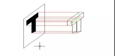
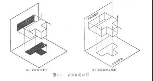
The projections of objects we see in daily life are all black shadows. As shown in Figure 1-1(a), the positioning plate adopts the orthographic projection method, and the resulting projection is black. It can only express the outline of the positioning plate, so when looking at the front of the object, the middle convex part of the front is not clear. Therefore, when we use the principle of orthographic projection, we need to replace the projection line with the line of sight, and draw all the contours of the object with the specified line. The resulting plane figure is called the view, as shown in Figure 1-1(b). . The view of looking directly at the object mentioned above is a popular way of obtaining the view using the principle of orthographic projection, that is to say, the view obtained by looking at the object with the line of sight perpendicular to the projection surface.
2.3 Three views of the object:
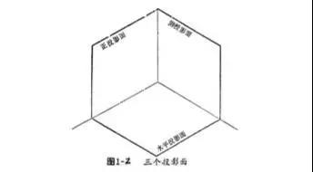
2.3.1 The figure of an object drawn on a projection surface by the orthographic projection method can only reflect the shape of the object in one direction. Therefore, three views are often used to express. That is, the commonly used front view, top view, and left view. The three-dimensional positions of the three projection surfaces of these three views are shown in Figure 1-2. The three projection surfaces are like a corner of the room, that is, like two walls and the floor that are perpendicular to each other.
2.3.2 Three projection planes and three views
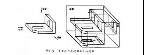
Figure 1-3 is a part, which is a view obtained by projecting to three projection planes from the three directions of the front, top and left. Front view-the view drawn on the front projection surface from the front of the part. It reflects the shape and size of the length and height of the part.
Left view-looking from the left side of the part to the right, the view drawn on the side projection surface. It reflects the shape and size of the width and height of the part.
Top view-looking down from the top of the part, the view drawn on the horizontal projection surface. It reflects the shape and size of the length and width of the part.
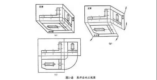
In order to see the pictures conveniently, the three three-dimensional views must be drawn on the same drawing, which means that the three projection surfaces must be spread out and flattened on the same plane, as shown in 1-4. How to unfold it? First, keep the front position in place, rotate the horizontal plane down by 90°, and then rotate the side face to the right by 90°, so that the unfolded three views are obtained.
2.3.3 The relationship between the view and the view (the relationship between the three views)
Objects have three directions of length, width, and height, as well as six directions up and down, left and right, and front and rear. Each of the three views reflects the shape and four directions in two directions, as shown in Figure 1-5. The main view reflects Thing
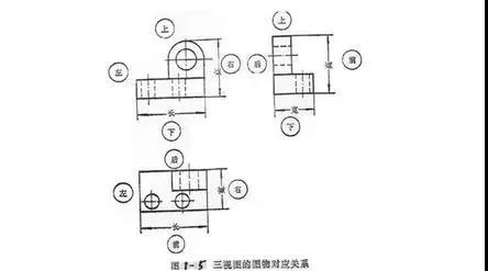
The length and height of the body and the top, bottom, left, and right orientations of the object; the top view reflects the length and width of the object and the left, right, front, and rear orientations of the object; the left view reflects the height and width of the object and the object Top, bottom, front, and back four directions; the shape, size and direction reflected by the three views are the length, width, height and the same direction of the same object. The main points are as follows: the left side of the left view (that is, the side close to the main view) represents the back of the object, the right side of the left view represents the front of the object, and the left side to the right represents the width of the object, and the top view In contrast to the width.
From the above figure (Figure 1-5), it can be seen that the two views together reflect the size of the object in the same direction, such as the front view and the top view, they both reflect the same length of the object, and the front view and the left view reflect the same height of the object. The top view and the left view reflect the same width of the object. Therefore, the following "third-class" relationship should be maintained between the three views, namely:
The main and top views are equal in length to the left and right; the main and left views are level up and down; the front and rear views are the same in the front and rear views.
In short, it means "the length is aligned, the height is even, and the width is equal".
2.4 How to see the part drawing
In actual work, I often encounter the problem of looking at the parts drawing. Looking at the part drawing is based on the content of the part drawing, imagining the structure and shape of the part, understanding the size and technical requirements of each part of the part, in order to formulate the method and process of processing the part, or as a technical reference material, and further on this basis Study the rationality of the part structure and be able to continuously improve and innovate.
2.4.1 General understanding of the role of parts on the machine
Get a part drawing, start with the title bar, understand the name of the part drawing, understand its material from the material column, and estimate the actual size of the part from the overall size of the drawing. Based on the existing actual knowledge, roughly understand its role. Understanding the role of parts and the relationship between related parts can lay a certain foundation for further analysis of the structural shape, size, and technical requirements of the parts.
2.4.2 Analysis view. Determine the structural shape of the part
Imagining the shape of a part is one of the main purposes of looking at a part drawing. Imagine and determine the shape of the part from the content expressed by each graphic. When looking at the picture, the line starts from the main view and looks at it together with other views. To understand the content of each graphic, it can be divided into the following three steps:
(1) First understand how many views, partial views, cross-sectional views, and cross-sectional views are composed of the part drawing you are looking at, and what is the relationship between them.
(2) Analyze the shape and analyze its constituent parts one by one using the law of projection (third-class relationship) until the shape of each part is understood.
(3) Through the above analysis of the shape and structure, the overall outline of the part can be imagined in combination, and the internal shape and detailed structure of each part can be further imagined.
2.4.3 Look at the technical requirements, understand the processing and manufacturing requirements
The technical requirements marked on the parts drawing are the quality requirements for the parts in the process of processing, inspection and installation. From the surface roughness code, dimensional tolerance, geometric shape and mutual position tolerance marked on the drawing, you can know the processing process and main processing surface of the part, and you can have a deeper understanding of the relationship between the shape, structure and size of the part. .
2.4.4 Synthesize, summarize and summarize to gain a comprehensive understanding of the parts