When selecting the bearings, it is always inevitable to perform the life of the bearings of the bearings, and the calculation of the bearing life school check must know the equivalent load when the bearings are running, and when the volume load is calculated by the bearing to afford the power, the bearings are performed by the bearing When the life is checked, the axial tolerance is always clear, that is, the axis bearing power calculation is required.
In the general bearing selection comprehensive records, there are calculation methods for converting bearing bearing power into equivalent loads, but there are often no bearing bearing to be calculated. Recently, engineers often ask questions about the calculation of bearing to be calculated, so they wrote an article.
The direction of the bearing system stress
The general axis system has two positioning fulcrum. We described the three -dimensional space of a shaft with three vertical space coordinate shafts: axis A, radial X, radial Y. Among them, the axial direction is the same direction as the axis direction. X and Y are two coordinate shafts perpendicular to each other in the radial plane of the axis system, respectively. (The radial plane is the plane where the axis radius is circular, which is perpendicular to the axial plane.) As shown in the figure below:

Under such a coordinate system, the bearings are installed on the bearing, and the bearing radius plane is on the radial plane in the figure above. Therefore, the force bearing the bearing can be decomposed into the division in these three directions. The bearing is x on the radial plane, and the force of the Y direction can be combined into a radial synergy. Usually, for the bearing, when the school check is calculated, regardless of the angle of the radial combined force on the radial plane, it is acceptable for the general rolling bearing, so we do not care about the specific angle, so we don't have to bring it will not have to bring it. This force is decomposed into x, y, and it can be directly transformed into a radial force FR. At the same time, we use FA for axial force. Therefore, when the bearing is analyzed, the radius and axial force are generally calculated.
The force analysis method of bearing in the bearing system
For a shaft system with a dual fulcrum support, it may be subject to the force in various directions. Therefore, before the analysis of force analysis, the force in all directions needs to be converted into the three directions of X, Y, and a The force of the bearing, finally the stress of the bearing radial to the plane into a radial load. This is the basic idea of bearing to be analyzed.
We use a horizontal motor for example. First of all, for a horizontal motor, if a radial load exists at a shaft extension, then the motor force is shown in the figure. In this example, we set the gravity G and the radial load on the same plane, so the saves saves the saves Go to the synthetic calculation process. In the actual situation of the project, the situation is often different, so the decomposition and synthesis in the above method will be calculated in the final calculation:
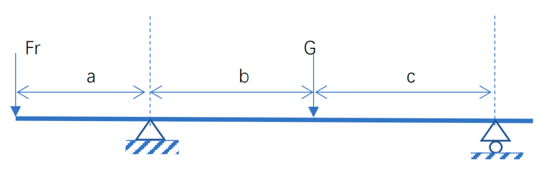
At this time, the motor rotor gravity G exists as radial force, and the distance between the load and the bearings is A, B, and C, respectively. When the shaft system is running, in addition to Zhou Xiang's free rotation, all other directions are stable, so the force of the two bearing can be calculated based on the torque balance. We call the left bearing as the 1st bearing, the right is No. 2.
FR*A = G*B-FR2*(B+C)
Therefore, you can calculate the radial load of the right bearing
FR2 = (G*B-FR*A)/(B+C)
At this time, FR1+FR2 = G+FR. So FR1 = G+FR-FR2.
Of course, FR1 can also be calculated based on the torque balance.
If there is an axial force in the motor, the bearing (left bearing) of the positioning end of the motor is affected by this axial load, and the shaft shaft direction load on the right floating end bearing is 0.
Overwhelm
In the previous paragraph, an engineer asked about the impact of the burden on the bearing bearing power, and could not find the calculation method in the information, so he asked for help. We still observe the above examples. In fact, radial load FR is not only a radial load, but also the radial load FR for the BC section system, but also forms a FR*A overtime torque. Therefore, it is not difficult to find that the calculation method is no different from the above calculation.
In some cases, the shaft system is covered with a pair of torque. At this time, if the general manual calculation is used, the default system is a rigid system. However, if the system deflection is considered, the situation is much more complicated. At this time, it is recommended to use some higher -level computing methods to analyze the axis bearing power. The general hand calculation method introduced above is not suitable for this occasion.